Explanations of the built-in, code-backed components in Simple and their properties. These can all be explored in-tool by browsing the KERNEL section of scripts in the simulation explorer.
Foundational
Fundamentals
entity
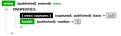
The most basic, common component type. Everything derives from entity.
- health: When 0 or less at the end of the frame, the component will die.
- { extra captures }: Has no code logic, but simply allows all components to receive captured components.
base

Even simpler than entity. Does nothing on its own and will always die at the end of frame. Useful for creating function-like components.
Simulation & Data Storage
Simulation
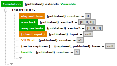
Simulations are like ‘levels,’ containers for other components. All non-Simulation components must belong to a single Simulation. Entry Point is the most commonly-used type of Simulation. Simulation is rarely used on its own except for as a data storage/sharing mechanism alongside other Entry Points.
- elapsed time: Duration, in seconds, Simulation has been alive.
- axis lock: Prevents physics from moving objects on any axes specified as
1. For example, ify = 1, then physics will not move anything up or down. Does not prevent script from modifying position outside of physics. - wrap extents: Defines the size of the simulation in units. Can be positive or negative (or a mix of both). If an axis is positive, when objects reach that edge they will wrap around to the other side. If an axis is negative, objects will not be allowed to move beyond it.
- { client input }: A collection of all viewers’
Inputplaying in the Simulation(s). This is required to exist per-Simulation, since in a situation with multiple Simulations, components must abide by the rule of belonging to only one Simulation.
Entry Point
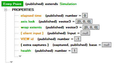
Effectively “a level”. Behaves just like a Simulation except it receives and is responsible for conjuring other Singletons ((conjured, published) components).
Only one Entry Point is allowed per sim file.
Save State
Note: Advanced usage only.
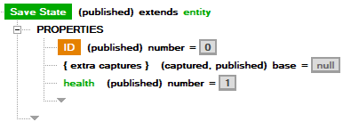
Special component that will store all of its properties’ values when destroyed and reconstruct them when conjured again. Only permits storage of value types (numbers, vectors, orientations).
- path: Location to place the save file - the save category.
- ID: ID of the Save State.
When conjuring a Save State extension, if no matching path/ID combination is found, run its property initialization as if it were a normal component. If a match is found, initializes its values to what they were when the component was destroyed.
Viewer Interaction
Components which interact with the view.
Viewable
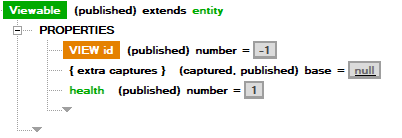
Any object which will want to be “seen” in the view, e.g. with a visual representation, must be a Viewable. All physics objects, for example, are Viewables.
You will generally have little reason to create a ‘raw’ Viewable, but it’s an intermediate for many objects.
- View ID: Unique ID to tell the view what resource will be used to represent the object. An example can be seen in the Melee content with the
Dialogcomponents. TODO: Add explanation for Dialog w/ resource files.
Input
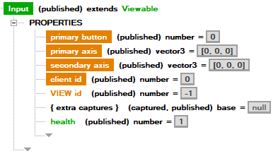
Every time a player/viewer joins the running game, an Input is conjured and placed into each Simulation’s { client input }. Mapping keys to input is specified within the parallel sim’s ini.
- primary button: 0 - released, 1 - just released, 2 - pressed, 3 - just pressed.
- primary axis: xyz values which can read 1 or -1 as button pressed states. Total of 6 usable buttons.
- secondary axis: (same as primary axis)
- client id: Unique ID generated per client, based on the client ID (name).
Physics Objects
Objects which have, at a minimum, position and rotation in the world. Some with properties for detecting interactions with other physics objects.
Physics Fundamentals
Transform
![]()
A base type of an object which can have position and rotation in space.
- position: Vector position.
- orientation: Orientation.
Velocities
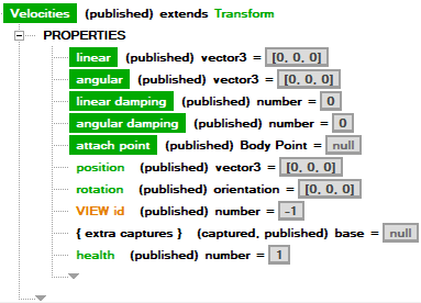
A base type of an object which can have velocity.
- linear: Linear velocity.
- angular: Rotational velocity.
- linear damping: Amount of damping (reduction) to linear velocity applied each frame.
- angular damping: Amount of damping (reduction) to angular velocity applied each frame.
- attach point: Optionally attach this object to a body point, causing it to inherit all changes to position from it and velocity from its parent transform.
Body Point
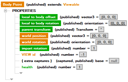
Body points serve a few purposes for creating relationships between different positions/orientations in space.
- Permitting the use of attach points of other objects.
- Helping with position/angle calculations, especially when using simulations with wrap extents, where comparing raw vector positions may yield false information if two objects are near the wrap edges.
- A convenience for converting between local and world coordinates.
Body points have a few special rules depending on which properties you’re using as an input (i.e. Assigning to properties) or as an output (i.e. Evaluating the properties). You will want to convert from local to world, or vice-versa:
- Assigning
local to bodyorworldvalues are mutually exclusive. You should only use one or othe other, and attempting to assign both will cause undesired results (likely theworldsettings will override thelocals). - Altering the world position of an already-conjured Body Point will not cause it to give updated
local to bodyvalues. Conjuring a new Body Point is required.
Properties:
- local to body offset:
- As an Input: xyz offset from the
parent transformto generate aworld position - As an Output: xyz offset of the Body Point from the
parent transform, based on theworld position.
- As an Input: xyz offset from the
- local to body rotation:
- As an Input: orientation offset from the
parent transformto generate aworld rotation - As an Output: orientation offset of the Body Point from the
parent transform, based on theworld rotation.
- As an Input: orientation offset from the
- parent transform: Transform the Body Point uses to relate its
localoffset/rotation. - world position:
- As an Input: The position in world coordinates to use to generate a
local to body offsetbased on theparent transform. - As an Output: The position in world coordinates produced by the
local to body offset.
- As an Input: The position in world coordinates to use to generate a
- world rotation:
- As an Input: The world orientation to use to generate a
local to body rotationbased on theparent transform. - As an Output: The world orientation produced by the
local to body rotation.
- As an Input: The world orientation to use to generate a
- impart rotation: Whether or not the body point imparts its rotation to objects using it as an attach point.
Overlapper
Not Implemented, see Collider, which functionally implements its properties.
Collider
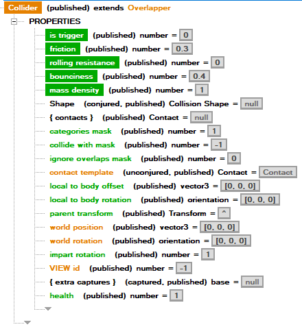
Colliders have Shapes which define their extents and can generate contacts. They must belong to a collision body.
- is trigger:
- With Raycast Shape: If 1, do not stop on first contact with another collider (i.e. pierces through and generates multiple contacts).
- With Rigid Body: Do not count as part of the Rigid Body for purpose of physical interactions.
- friction: 0-1 value of friction.
- rolling resistance: 0-1 value of rolling resistance.
- bounciness: 0-1 value of bounciness.
- mass density: ?
- Shape: Specified shape to use for defining the extents of the collider.
- { contacts }: Collection of contacts generated from physics.
- categories mask: Bit mask of categories this collider belongs to. Will only collide with Colliders that have matching bits in
collide with mask. - collide with mask: Bit mask of categories this collider will colllide with, based on their
categories mask. - ignore overlap mask: Does not generate contacts with other Colliders that match any bits (will still collide if allowed, just not generate contacts).
- contact template: (Advanced Use) When generating contacts, physics will generate the specified extension of
Contactupon collision.
Colliders extend Body Point and should specify the parent transform they belong to.
Contact
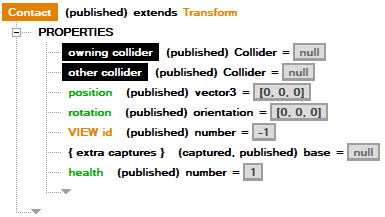
Contacts are generated in colliders’ { contacts } collection when a valid collision occurs.
- owning collider: The collider the contact belongs to (i.e. which one has it in its
{ contacts }). - other collider: The collider which is being contacted by the
owning collider. - position: Position in space of the intersection.
- rotation: Rotation of the intersection, based on the Shapes of the intersecting colliders. The up vector of the orientation is the contact’s normal.
- health: If a Contact’s
healthis 0 or less for any reason, it will not be generated. The default Contact has 1 health, but you may make an extension to Contact for use with Colliders’ contact template in conjunction with a property initialization that can conditionally set it to 0.
Note: Contacts are not allowed to run any script SECTIONS, but the UI doesn’t currently prevent you from trying. Don’t do it!
Collision Bodies
Collision Bodies are objects that move through space and usually have colliders.
Collision Body
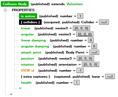
The basic Collision Body has no physical interaction with other objects, meaning it and its colliders are allowed to penetrate other Collision/Rigid Bodies.
- { colliders }: Colliders belonging to this Collision Body. Collision Bodies should not share Colliders.
Rigid Body
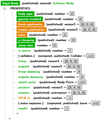
Rigid Bodies are physical Collision Bodies which interact in physics with other Rigid Bodies’ colliders. Physics will alter their velocities and position based on the interactions.
- body type
0: static - a Rigid Body which will never move (wall, level mesh).1: kinematic - (rarely used); a Rigid Body which physics controls but script cannot move around in any way.2: dynamic - a Rigid Body which moves via script control.
- gravity enabled: setting to 1 causes the body to be pulled downward on the y axis.
- force application: apply the specified amount of linear force to the Rigid Body this frame.
- torque application: apply the specified amount of rotational force to the Rigid Body this frame.
- mass: affects how much this Rigid Body moves and is moved by other Rigid Bodies relative to their mass.
Shapes
Shapes define the boundaries of a given collider.
Basic Shapes
Sphere Shape
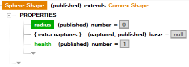
- radius: Radius of the sphere in units.
Capsule Shape
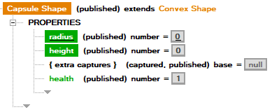
- radius: Radius of the capsule (x, z dimensions) in units.
- height: Height of the capsule (y dimension) in units.
Box Shape
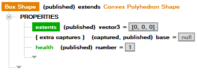
- extents: xyz dimensions of the box in units.
Mesh Shapes
Some shapes can use an obj file as complex mesh.
- mesh path: Path to the desired
objmesh. - scale: Scale (default 1) of the mesh.
Note: The tool does not give you much feedback about mesh shapes right now if something goes wrong (it likely just crashes at runtime). If your runtime is crashing, make sure your
objlooks correct, especially when trying to follow the rules of the convex shape.
Convex Mesh Shape
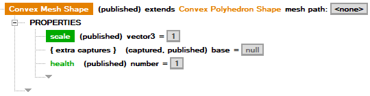
Convex mesh shapes must specify an obj which has no concave parts, with internal angles between edges/faces no greater than 180 degrees. Convex mesh shapes interact with both convex and concave mesh shapes.
Concave Mesh Shape
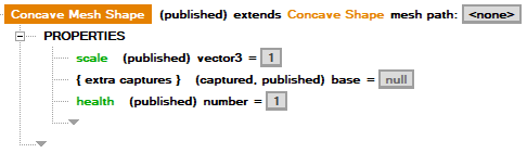
Concave mesh shapes can be made of any type of mesh, but cannot interact with any other concave mesh shapes.
Raycast Shape
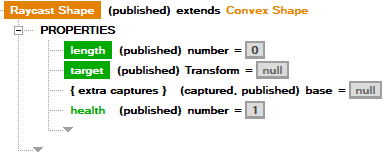
Raycast shape is a special shape that creates a line from the position of the collider to an optional end target. When its collider has is trigger set to 1, it will create multiple contacts; 0, it will stop on the first collider it touches.
- length: Length of the ray, starting from the position of the collider. If there is no target, the ray will just be a line oriented based on the collider.
- target: Optional Transform target for the ray. Will reorient the ray to face the target.
Navigation
Work-in-progress components for AI. Used in melee, don’t recommend using elsewhere at the moment.